
Introduction
In the metro ethernet world, customers order EPLs and EVPLs when they need PTP connectivity between two ports. Since we are beginning to get quite a bit of these circuits, I'm going to present a deep dive on how to deliver these services for the cell backhaul use case.
Glossary
AC - Attachment Circuit
NNI - Network to Network Interface
UNI - User to Network Interface
NID - Network Interface Device
TPID - Tag Protocol ID
PW - Pseudowire
RT - Route Target
RD - Route Distinguisher
RI - Routing Instance
RR - Route Reflector
Topology
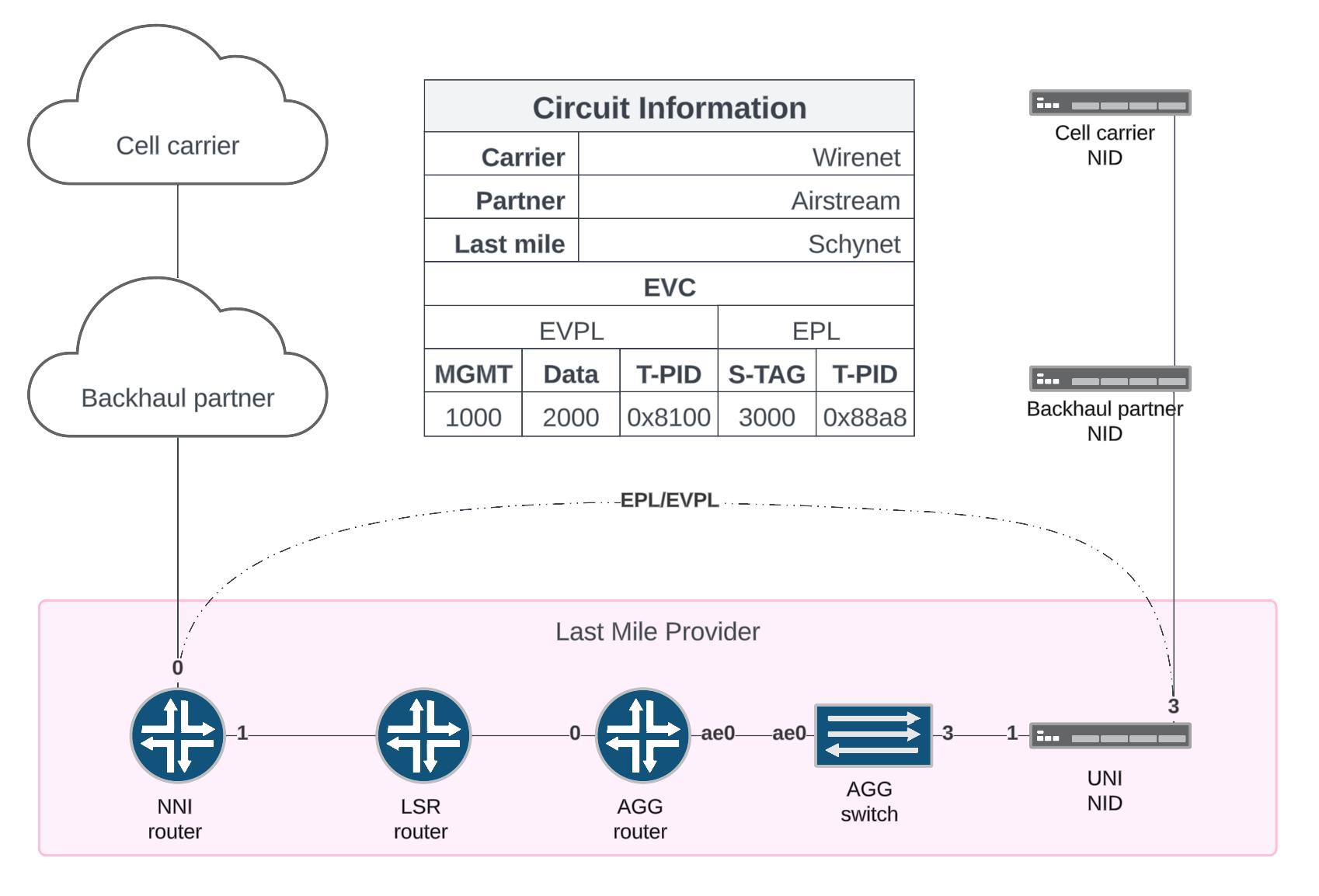
EVPL
The configuration
EVPL Configuration
UNI NID
To configure the UNI NID, we need to create vid-sets/L2 policies to match the cell carriers VLANs and traffic policies to send matching traffic out specific ports.
In the case of the port facing the customer, we will match incoming frames with tag 2000 and send them out port-1, the interface facing the service provider network.
In the case of the port facing the service provider network, we will match incoming frames with the tag 2000 and send them out port-3, the port facing the customer.
#vlan
traffic->vlan->vid-set->traffic-1->add:
    Name: CVLAN2000PORT1
    VLAN type: c-vlan
    VIDs: 2000
traffic->vlan->vid-set->traffic-3->add:
    Name: CVLAN2000PORT3
    VLAN type: c-vlan
    VIDs: 2000

#downstream-interface
traffic->polices->configuration->traffic-1->index-x:
    filter type: vid-set
    filter: CVLAN2000PORT1
    outgoing port: port-3
    evc mapping: none

#upstream-interface
traffic-policies->configuration->traffic-3->index-x:
    filter type: vid-set
    filter: CVLAN2000PORT3
    outgoing port: port-1
    evc mapping: none
Aggregation Switch
To configure the Aggregation Switch, we need to configure the interface facing the NID to add an outer tag and connect it to the upstream port facing the router.
The configuration here is a bit interesting, but essentially we match all vlans, on ingress we push a vlan-id and on egress we pop a vlan-id.
The vlan-id that is pushed and popped is set using the native-vlan-id command if there is no incoming vlan-id or the push vlan-id command if the frame already has a vlan-id
#downstream-interface
ge-0/0/3 {
    description CUST: SCHYNET. CID: 01;
    flexible-vlan-tagging;
    native-vlan-id 103;
    speed 1g;
    mtu 9192;
    encapsulation extended-vlan-bridge;
    unit 0 {
        vlan-id-list 1-4094;
        input-vlan-map push {
            vlan-id 103;
        }
        output-vlan-map pop;
        family ethernet-switching;
    }
}

#vlans
vlans {
    V0103 {
        interface ge-0/0/3.0;
        interface ae0.103;
    }
}

#upstream-interface
interfaces {
    ae0 {
        unit 103 {
            vlan-id 103;
        }
    }
}
Aggregation ROUTER
To configure the Aggregation Router, we need to configure the AC and the VPN it belongs to
In our topology, we demultiplex the service using 2 VLAN tags, therefore, the outer tag will determine which NID we are working with and the inner tag determines which service.
In this case, VLAN 103 is our NID and VLAN 2000 is the service. Since the frame is coming in as a vlan and leaving as an untouched payload, the encapsulation needs to be vlan-ccc.
For the VPN, we will be using EVPN to signal the PW but there are several other ways to do this including: BGP w/AF, LDP, RSVP+CCC, and FEC129.
Since this is a E-LINE service, we do not want to learn MACs.
As with any MPLS VPN, you need to create your RT/RD and add your interfaces to the RI.
#interface
interfaces {
    ae0 {
        unit 103 {
            description "CUST: SCHYNET. CID: 0101";
            encapsulation vlan-ccc;
            vlan-tags outer 103 inner 2000;
        }
    }
}

#routing-instance
routing-instances {
    EVPN-VPWS-CID-0101: {
        instance-type evpn-vpws;
        protocols {
            evpn {
                no-mac-learning;
                no-normalization;
                interface ae0.103 {
                    vpws-service-id {
                        local 502;
                        remote 501;
                    }
                    control-word;
                }
            }
        }
        interface ae0.103;
        route-distinguisher 10.255.255.100:5011;
        vrf-target target:65000:5011;
    }
}
NNI Router
The NNI router is responsible for adding and removing the service provider outer tag when data flows between the service provider and the upstream partner.
Similar to the aggregation switch, when data is received from the upstream partner, it will have a vlan-id on it already but we will add an additional tag.
#interface
interfaces {
    et-0/0/1 {
        description "PEER: Wholesale NNI";
        flexible-vlan-tagging;
        mtu 9192;
        encapsulation flexible-ethernet-services;
        unit 2000 {
            description "EVPN-VPWS-CID-0101";
            encapsulation vlan-ccc;
            vlan-id 2000;
            input-vlan-map {
                push;
                vlan-id 103;
            }
            output-vlan-map pop;
        }
    }
}

#routing-instance
routing-instances {
    EVPN-VPWS-CID-0101 {
        instance-type evpn-vpws;
        protocols {
            evpn {
                no-mac-learning;
                no-normalization;
                interface et-0/0/1.2000 {
                    vpws-service-id {
                        local 501;
                        remote 502;
                    }
                    control-word;
                }
            }
        }
        interface et-0/0/1.2000;
        route-distinguisher 10.255.255.102:5011;
        vrf-target target:65000:5011;
    }
EVPL
The controlplane
EVPL Controlplane
Building L3 MPLS VPNs tends to be easier for newer engineers than L2 VPNs. In this section lets step through each part of the control plane.
Some assumptions:
- RRs instead of full mesh iBGP
- Loopback-to-loopback connectivity via IGP and useable routes in inet.3
- RRs and clients have BGP AF evpn enabled
- All required protocols are established
Step 1
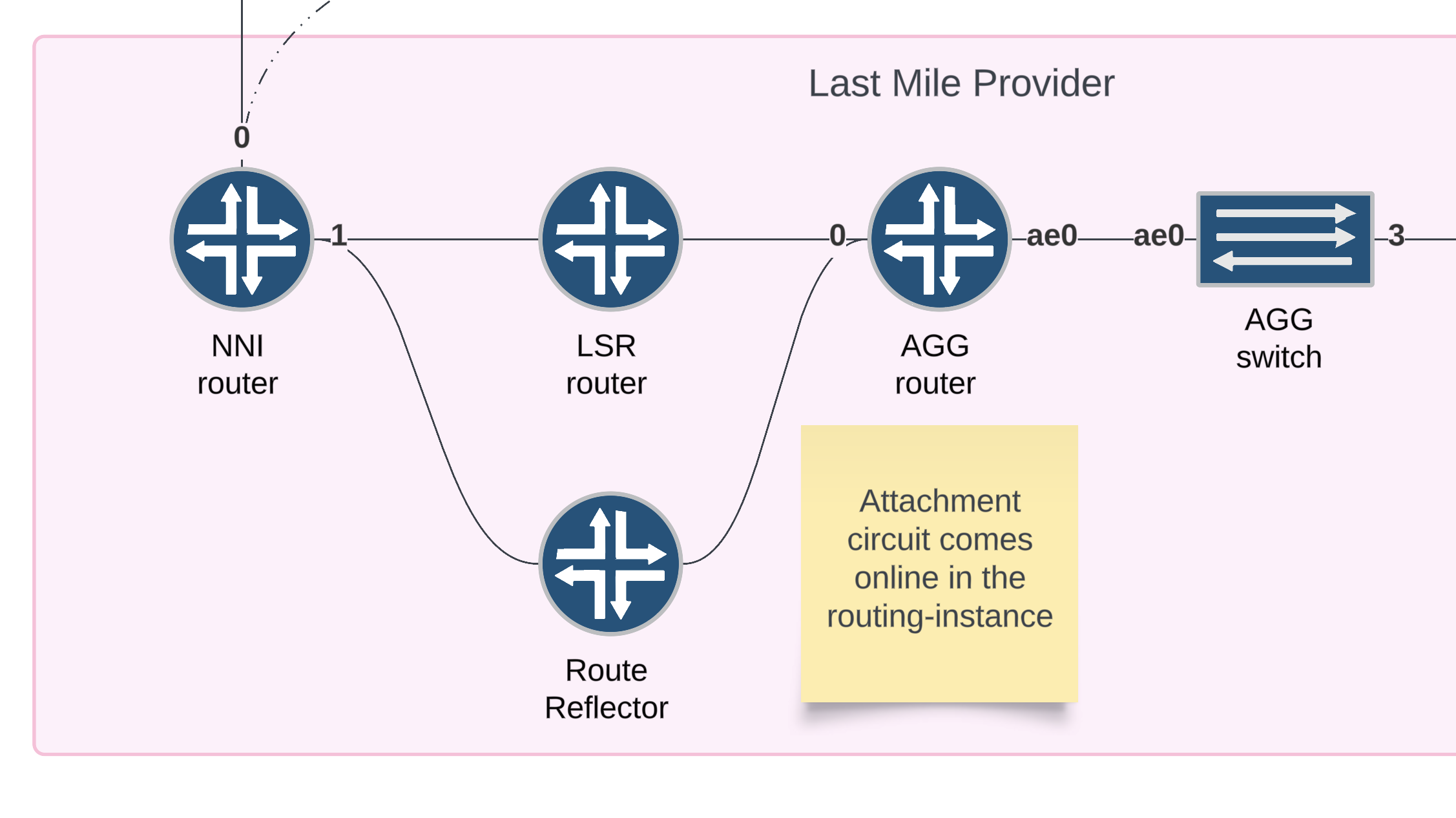
Verification (interface up)
show interface ae0.103 terse
Result (interface up)
Interface               Admin Link Proto    Local                 Remote
ae0.103                 up    up   ccc
Verification (installed route)
show route table EVPN-VPWS-CID-0101.evpn.0
Result (installed route)
1:10.255.255.100:5011::0::502/192 AD/EVI
                   *[EVPN/170] 21:18:12
                       Indirect
Step 2
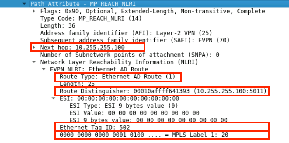
For E-LINE EVPL services signaled by EVPN, there is only a single route type used: Type 1 (AD/ESI). This route will be advertised once the AC is up.
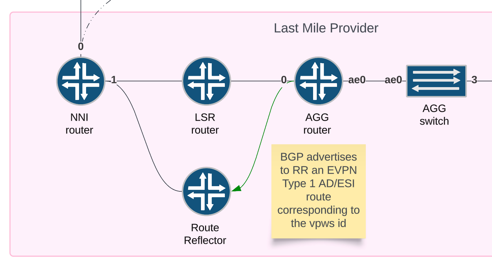
Verification
show route advertising-protocol bgp 10.255.255.103 table EVPN-VPWS-CID-0101.evpn.0 extensive
Result
EVPN-VPWS-CID-0101.evpn.0: 2 destinations, 2 routes (2 active, 0 holddown, 0 hidden)
* 1:10.255.255.100:5011::0::502/192 AD/EVI (1 entry, 1 announced)
 BGP group core-clients type Internal
     Route Distinguisher: 10.255.255.100:5011
     Route Label: 20
     Nexthop: Self
     Flags: Nexthop Change
     Localpref: 100
     AS path: [65000] I
     Communities: target:65000:5011 evpn-l2-info:0x4:control-word (mtu 0)
Packet capture
Step 3
The route reflector receives this route and resolves the next hop. If the route is useable, IE the NH can resolve to a route in the inet.3 table, then the route is reflected assuming default bgp policies.
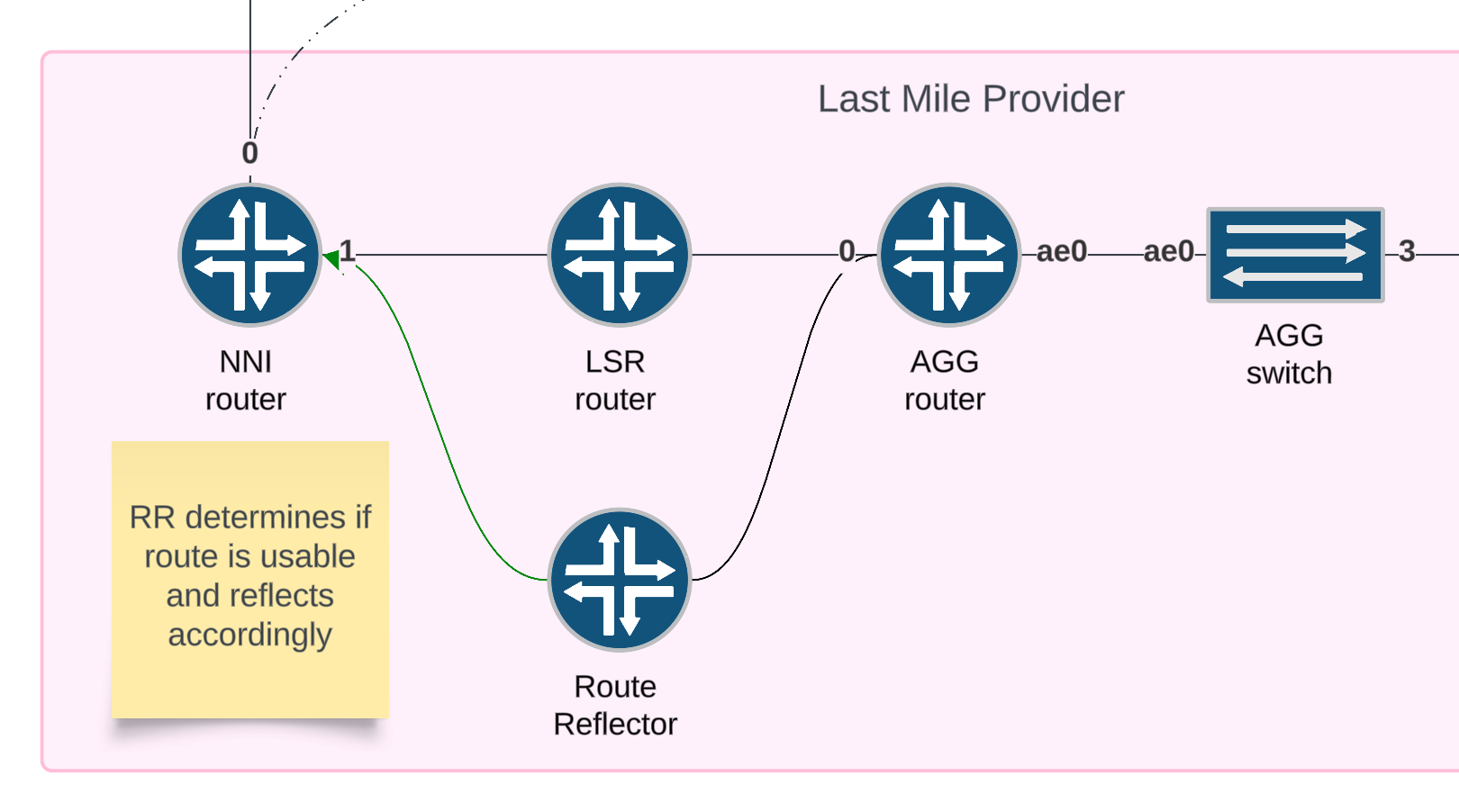
Verification
show route receive-protocol bgp 10.255.255.100
show route advertising-protocol bgp 10.255.255.102  bgp.evpn.0 extensive
Result
bgp.evpn.0: 2 destinations, 2 routes (2 active, 0 holddown, 0 hidden)
* 1:10.255.255.100:5011::0::502/192 AD/EVI (1 entry, 1 announced)
 BGP group core-clients type Internal
     Route Distinguisher: 10.255.255.100:5011
     Route Label: 20
     Nexthop: 10.255.255.100
     Localpref: 100
     AS path: [65000] I
     Communities: target:65000:5011 evpn-l2-info:0x4:control-word (mtu 0)
     Cluster ID: 0.0.0.1
     Originator ID: 10.255.255.100
Step 4
The NNI router receives the evpn route and copies the route to the EVPN-VPWS routing instance due to the vrf-target import policy. If the route is usable, then it is installed.
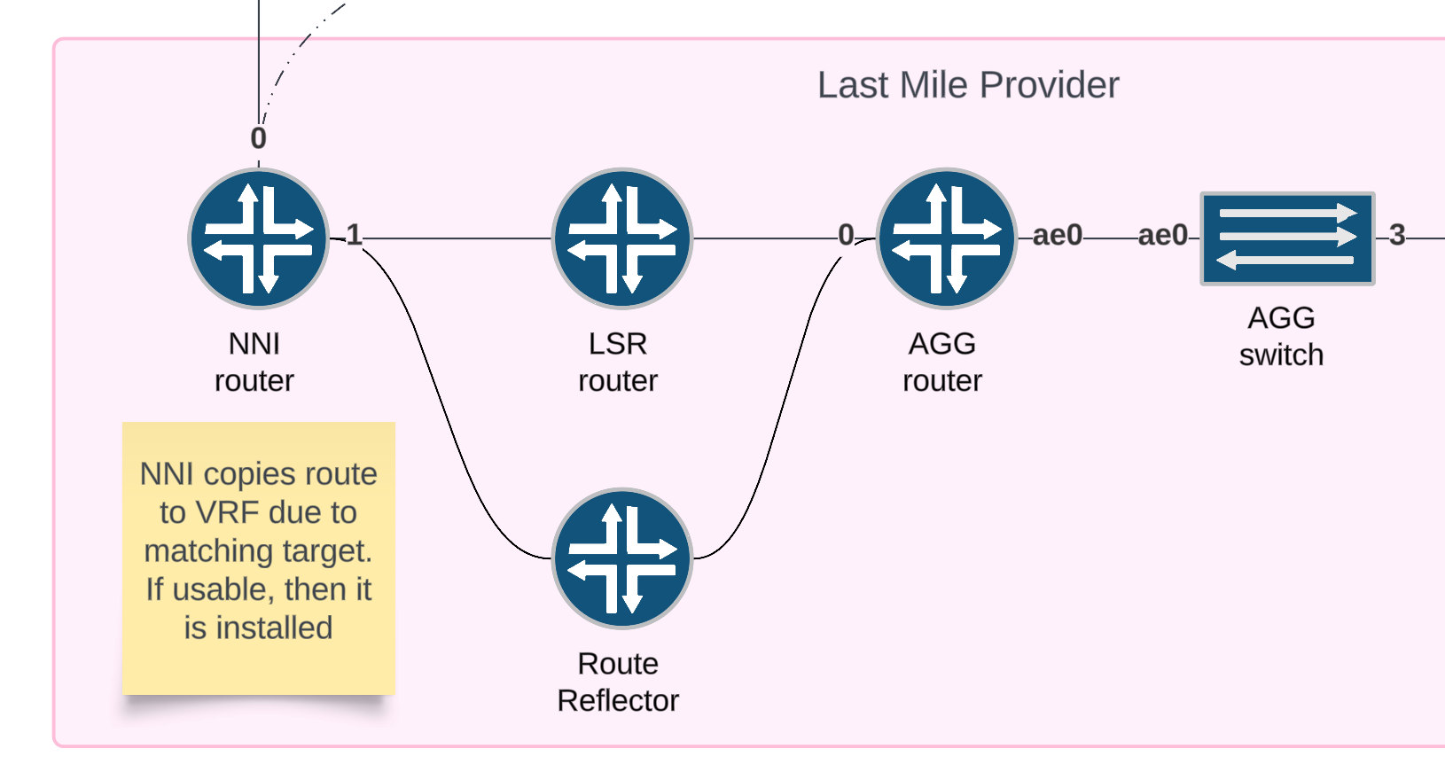
Verification (received route)
show route receive-protocol bgp 10.255.255.103 table EVPN-VPWS-CID-0101.evpn.0 extensive
Result (received route)
EVPN-VPWS-CID-0101.evpn.0: 2 destinations, 2 routes (2 active, 0 holddown, 0 hidden)
* 1:10.255.255.100:5011::0::502/192 AD/EVI (1 entry, 1 announced)
     Import Accepted
     Route Distinguisher: 10.255.255.100:5011
     Route Label: 20
     Nexthop: 10.255.255.100
     Localpref: 100
     AS path: I  (Originator)
     Cluster list:  0.0.0.1
     Originator ID: 10.255.255.100
     Communities: target:65000:5011 evpn-l2-info:0x4:control-word (mtu 0)
Verification (installed route)
show route table EVPN-VPWS-CID-0101.evpn.0
Result (installed route)
EVPN-VPWS-CID-0101.evpn.0: 2 destinations, 2 routes (2 active, 0 holddown, 0 hidden)
+ = Active Route, - = Last Active, * = Both

1:10.255.255.100:5011::0::502/192 AD/EVI
                   *[BGP/170] 00:03:59, localpref 100, from 10.255.255.103
                      AS path: I, validation-state: unverified
                    >  to 10.0.0.17 via et-0/0/4.0, label-switched-path tope
EVPL
The dataplane
EVPL High Level Packet Flow
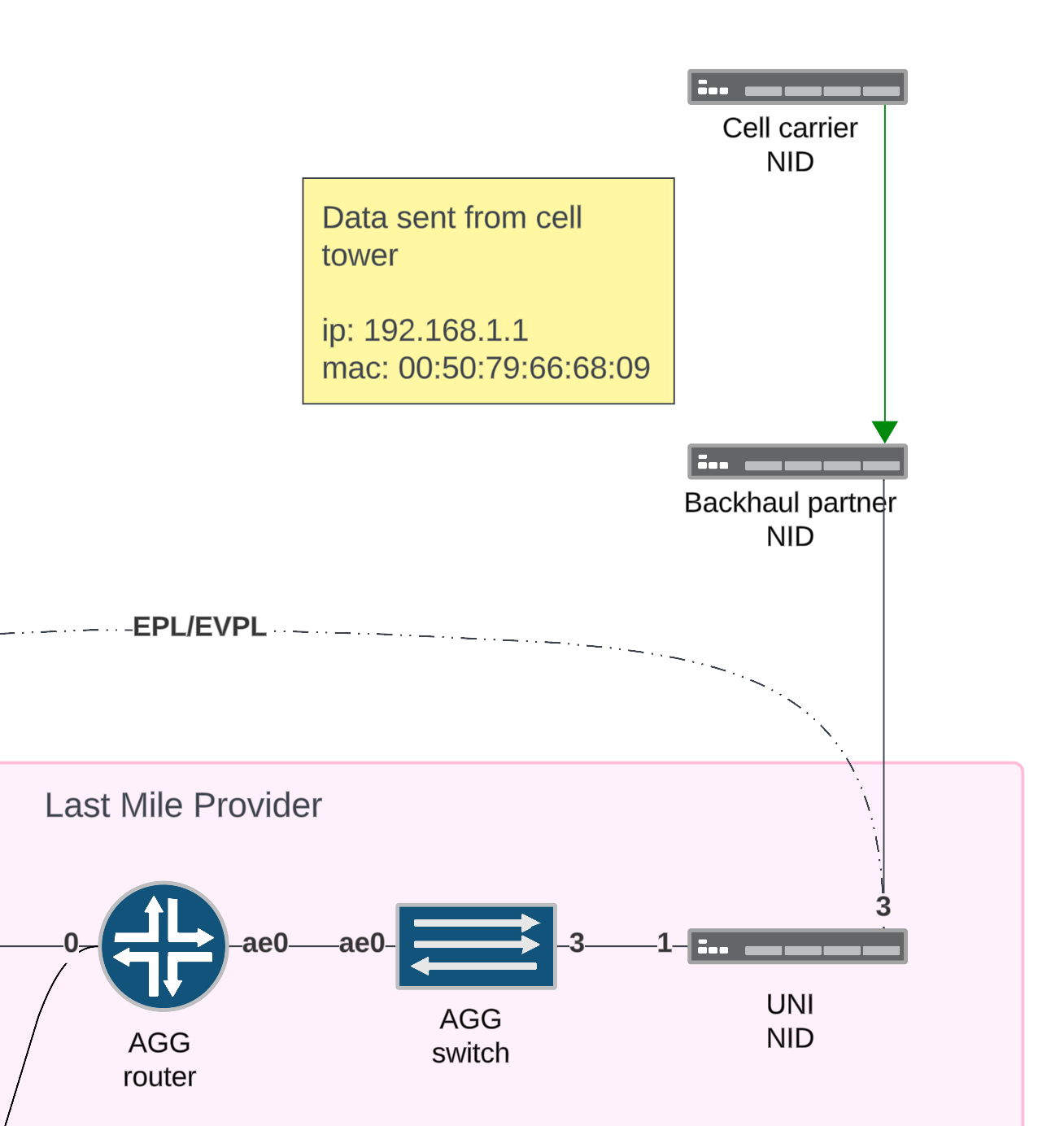
- Encapsulated Data is sent from the cell carrier NID upstream
- When the frame reaches the UNI NID, the Accedian match policy will forward the frame out the uplink port unchanged.
- When the frame reaches the AGG switch, we encapsulate it with a 802.1Q tag with TPID:
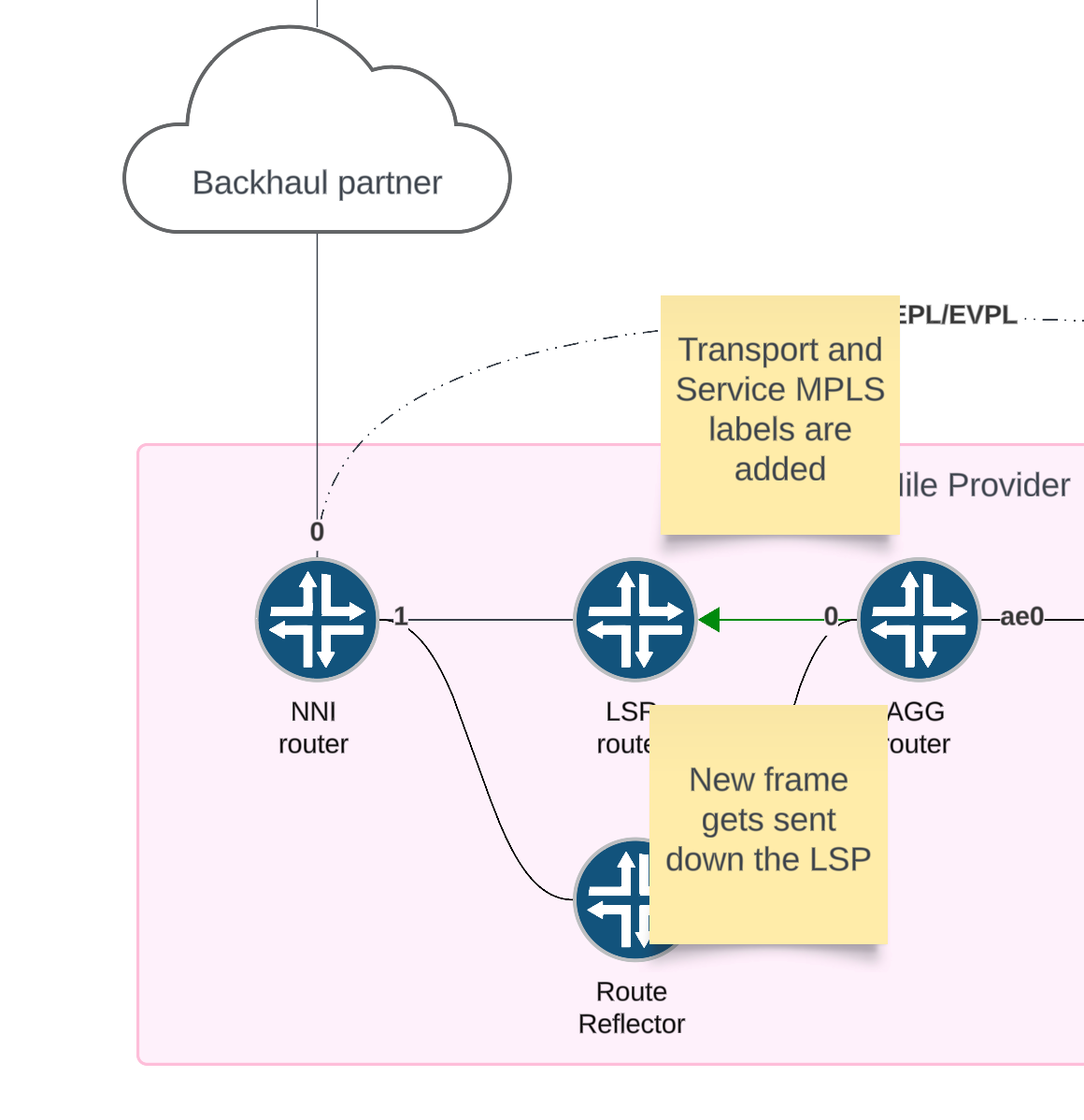
0x8100. At this point, there could be several tags now on the frame - When the frame reaches the AGG router, we use a combination of the outer and inner tag to demultiplex the traffic into the PW. The matching frames are then encapsulated with the service label. Recursive next hop resolution on the protocol next hop resolves in the inet.3 table to the LSP where the transport label is added to the frame. The frame is then sent to the egress interface towards the remote router.
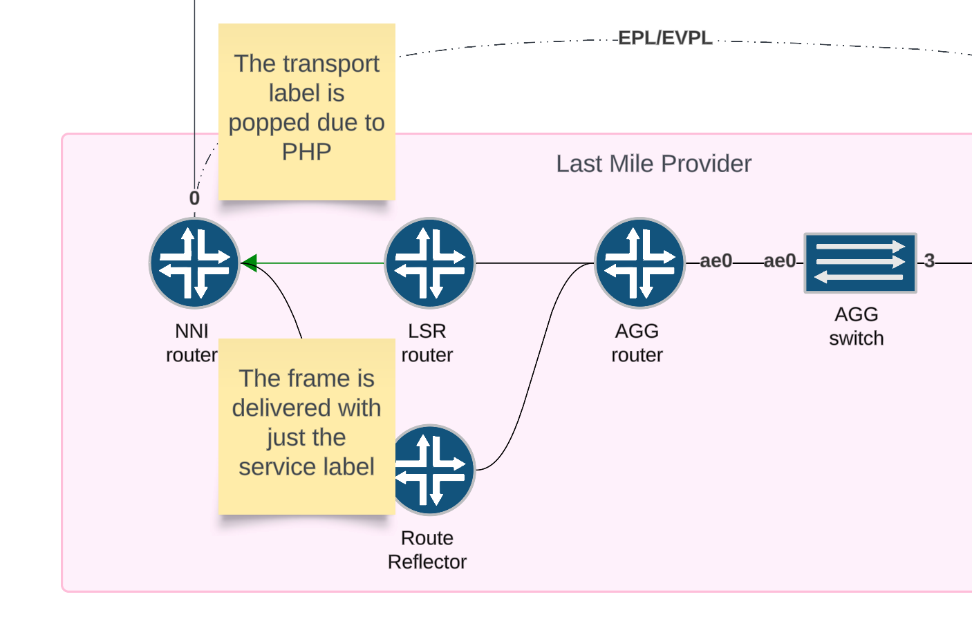
- When the frame arrives at the penultimate router, the transport label is popped and the frame is sent towards the final PE router with just the service label.
Connection information
Step 1
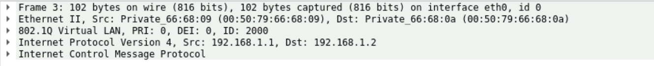
Data is sent from cell carrier NID upstream.
Packet capture
Step 2
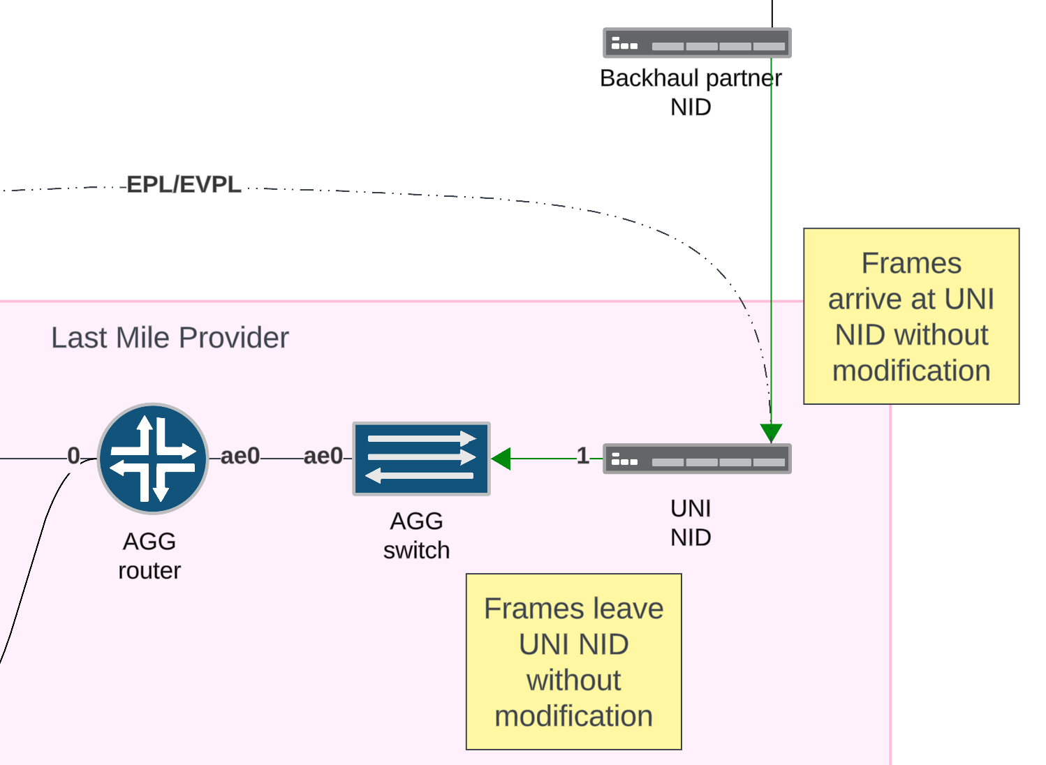
The backhaul partner forwards the frames unmodified to the UNI NID and the UNI NID forwards the frames unmodified to the AGG switch.
Step 3
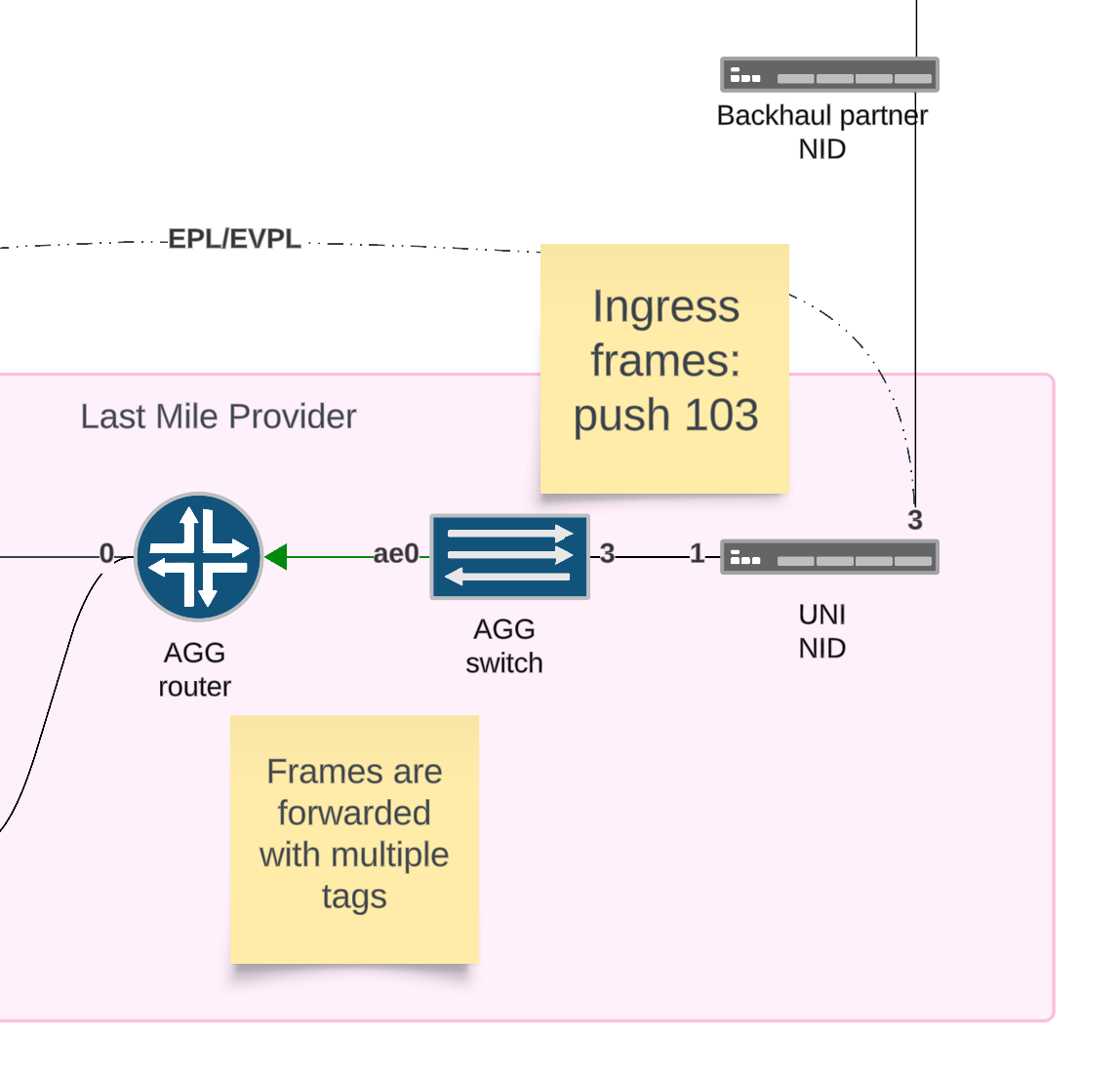
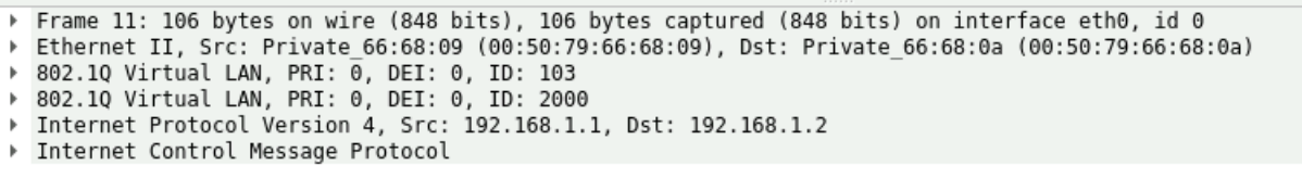
Frames received on the AGG switch are encapsulated with an outer tag that uniquely identifies the circuit. Then the frames are flooded or forwarded per normal mac-learning rules.
Packet Capture
Step 4
The router uses the combination of inner and outer tags to match the correct traffic. Then the data is encapsulated and sent over the PW.
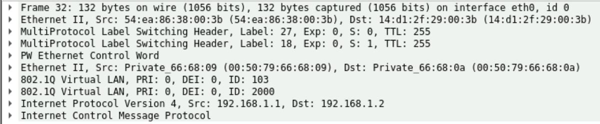
Verification (service label)
show route table EVPN-VPWS-CID-0101.evpn.0 detail
Result (service label)
1:10.255.255.102:5011::0::501/192 AD/EVI (1 entry, 1 announced)
        *BGP    Preference: 170/-101
                Route Distinguisher: 10.255.255.102:5011
                Next hop type: Indirect <---[RECURSIVE]
                Protocol next hop: 10.255.255.102 <-----[INET.3 DST]
                Route Label: 18 <----- [SERVICE TAG]
Verification (LSP, Transport Label)
show route 10.255.255.102 table inet.3 detail
Result (LSP, Transport Label)
inet.3: 8 destinations, 8 routes (8 active, 0 holddown, 0 hidden)
10.255.255.102/32 (1 entry, 1 announced)
        *RSVP   Preference: 7/1
                Next hop type: Router, Next hop index: 51034
                Next hop: 10.0.0.14 via et-0/0/6.0, selected
                Label-switched-path tonni
                Label operation: Push 27
Packet Capture
Step 5
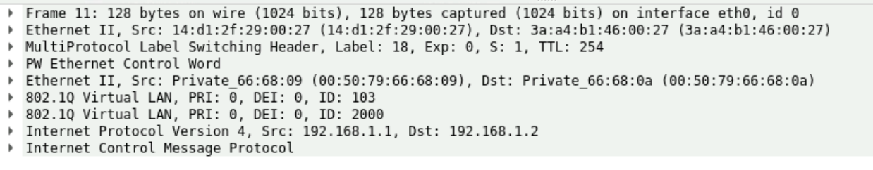
Due to penultimate hop popping, the transport label is popped at the second to last mpls router. Then the frame is delivered to the final PE router with only the service label. This can be seen in the mpls.0 route table as action=pop for the transport label we are using.
Verification
show route table mpls.0 detail
Result
27(S=0) (1 entry, 1 announced)
        *RSVP   Preference: 7/1
                Next hop type: Chain, Next hop index: 51051
                Label-switched-path tonni
                Label operation: Pop
Packet Capture
EVPL
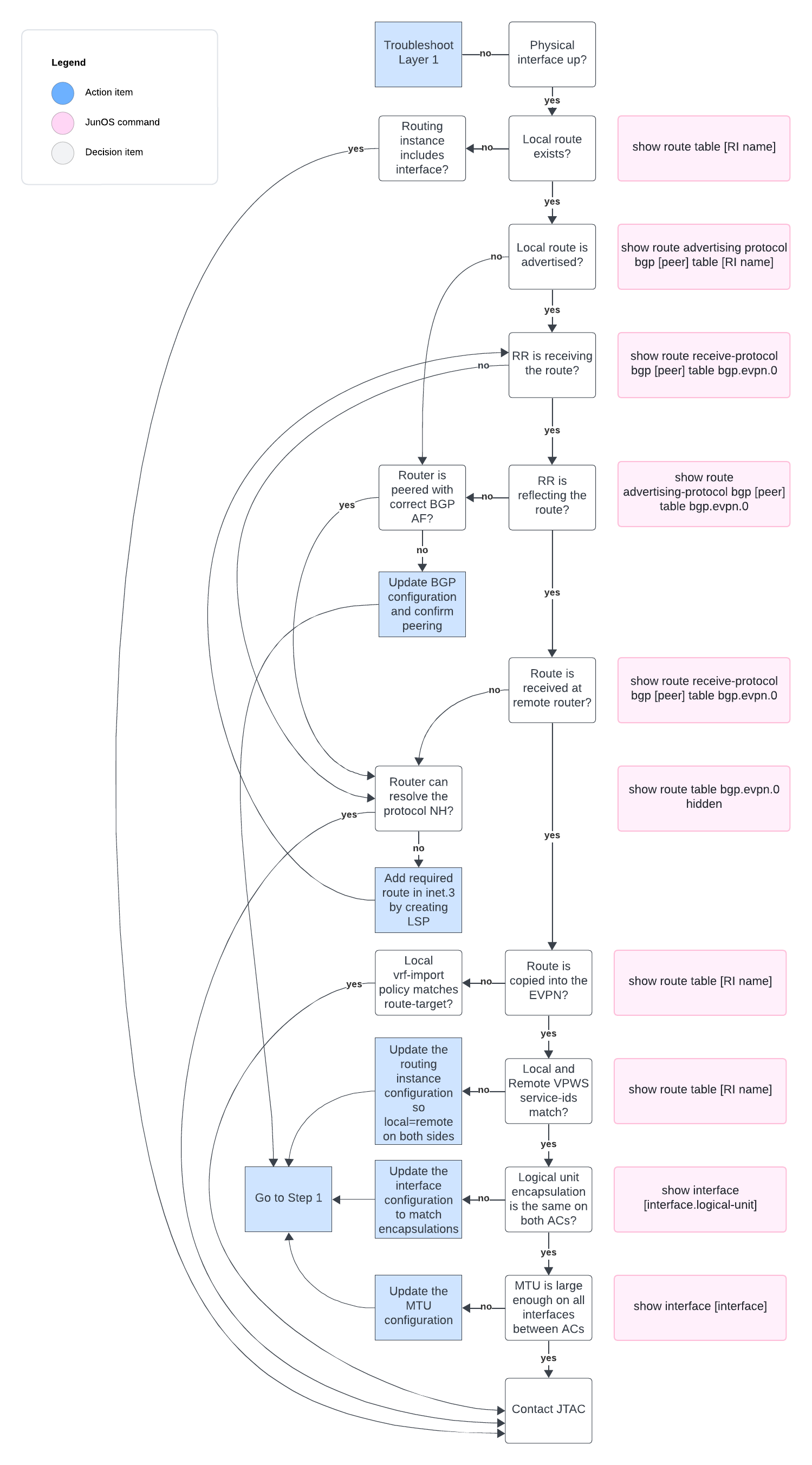
Troubleshooting flowchart
EVPL
Summary
Summary
In this deep dive, we have discussed configuring, verifying and troubleshooting both the control plane and dataplane of an EVPN signaled VPWS to provide the EVPL service.
At this point, you should have the tools required to sell this service to your customers and feel confident you can support it.

